 DataModem DataModem
Introduction
As part of a proof of concept project, I aimed to create a versatile data modem using a standard Arduino UNO, with minimal additional hardware. Initially, the goal was to receive and decode RTTY signals, but it quickly evolved to include transmission capabilities, changes in tones, and even reversals. You probably know how these developments tend to unfold.
Software Implementation
While I enjoy tinkering with Arduino hardware, I am not particularly enthusiastic about the Arduino IDE due to its limitations in flexibility and portability. Therefore, despite recently shifting away from the famous blue programmer and embracing the standard bootloader, I still opt for standard .C and .H files, create my Hardware Abstraction Layer (drivers), and use a Makefile to handle compilation, flashing, and related tasks.
Hardware Selection
To streamline the project, I endeavored to handle as much as possible through software, minimizing the need for additional off-the-shelf hardware components. I chose a standard Arduino Uno board as the platform for the entire device. This board houses an Atmel328p Microcontroller, which I employ as a sort of Digital Signal Processor. Although a homemade Arduino shield provides some signal conditioning, it could potentially function without it.
Receiving
For receiving, the audio signal is directed nearly directly to one of the I/O pins. This particular pin generates an interrupt on both the leading and trailing edges of the audio signal. By utilizing one of the Microcontroller's timers, we can measure the period time, thereby determining the frequency. Once the MARK and SPACE tones are decoded, they are input into a real-time software-based 5-bit UART shift implementation. This process extracts Baudot code, which is then converted into ASCII and sent out through the Arduino's serial port.
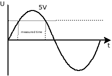 Period Time Measurement
Transmitting
Transmitting Baudot code essentially reverses the process. Text received via the Arduino's serial port is converted into Baudot, and audio tones are generated using a timer that toggles one of the I/O pins. This is followed by a relatively simple Low Pass Filter.
PCB
To simplify the setup, we created an Arduino Shield. This PCB includes a digital audio input, an analog input to support modern digital modes, an audio output followed by a LPF, and a transistor for switching between transmit and receive modes.
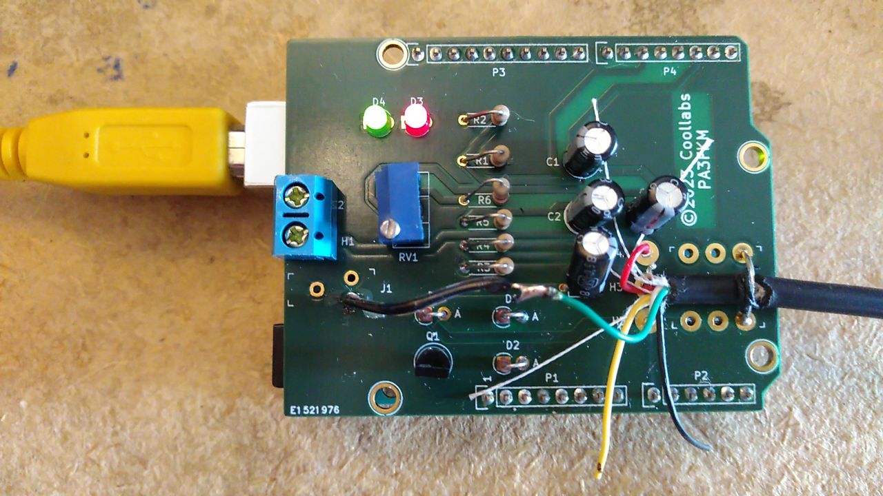 Arduino shield
Results
The decoding process was mainly tested using the German Weather Forecast station DDK2 on 10.100 MHz. Additionally, successful transmissions between two Baofeng handheld radios were achieved.
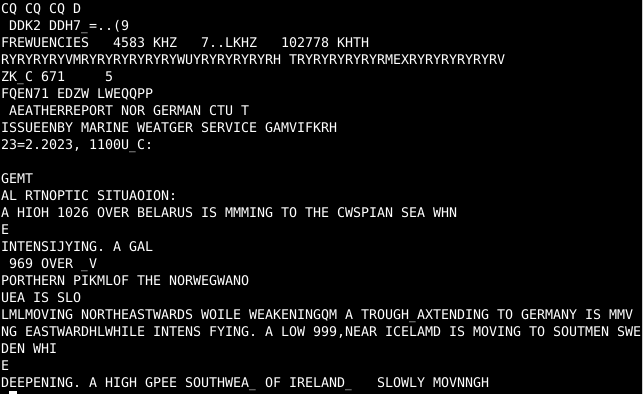 DDK2 Log
Other References
For more information about the inception of this project, you can read a Dutch article in a free online magazine on page 26. The article can be found in DaruMagazine.
DaruMagazine